Tips and tricks
Drive not running:
- Check power supply directly on drive unit.
- Check limit switch setting and adjust if necessary.
- Check motor connection: Tighten down contacts.
- Check motor protection switch, check setting (refer to type plate for nominal current).
- On drives with single-phase motors, the temperature monitoring function (WSK) on the motor may have responded / tripped: Give the motor time to cool down.
Run across the limit position:
- Check rotational field.
- Check that actuator rings are firmly seated and that limit switches are set correctly.
- Check electrical switch function of switches HI and HII, and if necessary also for additional switches SI and SII.
- Limit switch roller must not be tilted, see assembly instructions.
- Check switch function of control unit.
- You will find an END 20 animation on our homepage.
Oil loss
- Check assembly position of bleed screw.
Drive only rotates in one direction
- Line N swapped with line L.
- WSK coil protection contact activated (standby mode). See operating instructions.
No temperature reading on display panel
- Check power supply at ventilation controller.
- Check fuses.
- Check temperature sensor (see operating instructions).
- Temperature sensor connected?
Position of ventilation does not match parameter in operating menu 1
- Check run-time recording function, and run it if necessary (see operating instructions).
Ventilation fails to open completely
- Check Max. limit position.
Ventilation fails to close completely during rainfall
- Check Min. limit position.
Ventilation fails to close during rainfall
- Check rain sensor.
For other faults, refer to operating instructions.
No temperature reading on display panel
- Check power supply at ventilation controller.
- Check fuses.
- Check temperature sensor (see operating instructions).
- Temperature sensor connected?
Ventilation fails to close during rainfall
- Check rain sensor.
- Use the special lubricant specified by the manufacturer.
- Depending on application, lubricate rack at least once a year.
- Tightening torque see operating instructions.
All the work described must be carried out by skilled and trained personnel. Skilled and trained personnel‘ are people whose education, experience and training (e.g. installation fitters certified by Lock) as well as knowledge of applicable standards and stipulations, work safety specifications and on-site conditions at the company authorize them to be responsible for the safety of the system, to carry out the activities required in each case and, in that process, to identify and to be able to prevent potential hazards.
Setting the on-site motor protection switch
- set the motor protection switch on the on-site control system to the connected load according to the electric motor rating plate.
- start the electric drive in on/off mode.
- operate the electric drive under load in the operating range between the switch-off points. Measure and check the current consumption of the motor during a complete opening and closing process.
- set the motor protection switch to a value 5% higher than the measured value. The set value must not exceed the connected load of the motor by more than 3% [overload protection].
Assembly of EWA 10–EWA 16 // Power drives
Please note the procedure for mounting the gearbox breather.
- You will find the bleed screw (M6 x 10 with 2 mm axial bore) in the rubber gasket under the limit switch cover.
- Establish location of bleed screw on illustration, based on installation position.
- Replace located screw with bleed screw (M6 x 10 with 2 mm axial bore). Reuse existing copper seal.
- Insert replaced screw back in rubber gasket on limit switch compartment.
Note:
- For an active water application (e.g. cleaning with high pressure cleaner) our power drives are not intended (see instructions) and must be sufficiently protected (e.g. by a cover)
- Please refer to operating instructions for assembly positions and gearbox breather on the EZW 64.
Our EWA power drives all have the protection class IP 55 according to DIN EN 60529.
That means they:
- Are protected against dust in harmful quantities.
- Have a complete protection against accidental contact.
- Are protected against water jets from any angle.
For outdoor use, we recommend the use of the A60 option. This enables long-term functional reliability in protected outdoor areas. Protected outdoor area includes a cover for the electric actuators to keep out splashing water or direct sprinkling (see also instructions).


In these installation positions the drives must be protected against water application (e.g. by a cover).
KKS Assembly
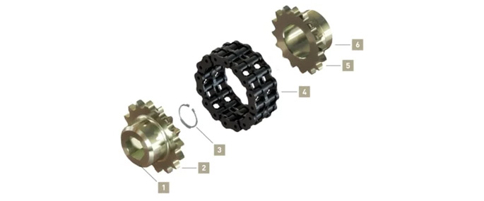
- Rotate coupling halves ( 1 ) and ( 6 ) until teeth ( 2 ) and ( 5 ) are arranged identically. Fit retaining ring ( 3 ) to end of shaft drive.
- Place double chain ( 4 ) around teeth on coupling halves ( 2 ) and ( 5 ) with ends of chain arranged at top.

Assembly B:
- Fold up end links ( 8 ) on the second chain.
- Insert connecting link ( 7 ) through end links of the first chain.
Assembly C:
- Insert two connecting plates ( 9 ) to connecting link.
- Fold end links ( 8 ) back down again.
- Insert connecting link ( 7 ) right through.
Assembly D:
- Slide on connecting plate ( 10 ) and engage spring connection ( 11 ) in recesses in connecting link .
Maintenance: Apply light coat of lube oil to chain on an annual basis. Remove surplus oil.
Assembly EZD 52
- Rack & pinion units for actuation of lightweight panels.
- Split steel rack & pinion units in revolutionary new design for roof or side vents in all kinds of greenhouses, e.g. open roof houses.
- Interlocking two-piece steel pinion 1”. Push-to-lock plastic housing works as bearing and sliding block for rack.
- Racks available in various lengths, straight or curved. Made from galvanized steel, 3 mm wall thickness. Load 500 N = 115 lbf.
- Quicker installation due to unique design.
- Quicker replacement without disassembly of drive shaft.
- Compatible with standard steel rack + pinion.
- Also available as EZD 51 in cost effective one-piece design.
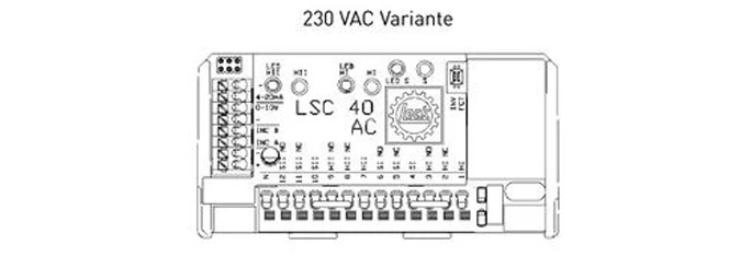
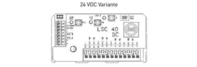
LSC 40.10 // Control unit
- High-precision mechatronic control unit with integrated limit stop disengagement and integrated additional switches.
- High-quality, reliable disengagement at limit positions.
- !!! AC and DC versions !!!
- Precise, fast and simple adjustment without connection to a power supply.
Option:
- Integrated LPR position sensor.
Notices:
- Please select the LPR option when ordering your EWA because retro-fitting is a costly proposition.
- The control unit is only suitable for protecting the equipment. It must not be used for personal protection purposes.
- When placing an order, pay particular attention to the correct choice of AC / DC variant.
- For operation, you need to have a 7-core cable.

Before you start setting the monitoring unit, please read the enclosed instructions through carefully and pay attention to the safety information.
- Screw on the limit switch cover with gasket and store it safely.
The following switch functions are specified: LEDs HI and HII light up red. Switch HI switches off direction of rotation I. Switch HII switches off direction of rotation II.
- Reset the setting. At the same time, press and hold down buttons S, HI and HII until LEDs HI and HII light up red.
- Adjust the limit stops by attaching a drill fitted with the attached hex-head bit to the motor shaft.
- Use the drill to rotate the shaft in direction of rotation ’I’ until you have reached the desired limit position (see direction of rotation arrow on housing beside the output shaft). It is also possible to start with the limit position for ’HII’ (see Step 5). Once the desired limit position has been reached, save limit position ’HI’. To do this, hold down button ’S’ and also press button ’HI’ until LED ’HI’ changes from red to green.
- Once the limit position for ’HI’ has been set, rotate the drive in the opposite direction, as described above, into limit position ’II’ (see direction of rotation arrow beside the output shaft). Once the desired limit position has been reached, you can save limit position ’HII’. To do this, press and hold down the ‘S’ button while also pressing the ‘HII’ button until LED ‘HII’ changes from red to green.
- Then check whether the limit positions have been set. To do this, press the ‘S’ button: All three LEDs (LED ‘HI’ / LED ‘HII’ / LED ‘S’) must light up green. If they do not, repeat the setting procedure for limit positions, as described above.
- Connect up the drive to the power supply unit. Fit the cover and the rubber gasket using the 4 screws and the 4 copper washers provided.Then connect up the electrical power supply and start up the unit (test run) in accordance with the instructions in the EWA Operating Manual (Electrical connection, Chapter 6 ff. and Initial start-up, Chapter 6.5)
END 20.20, END 20.40 // Limit switch systems

- Very precise differential gear limit switch for 580 (EWA 10– EWA 14 / EZW 64) and/or 395 (EWA 16) shaft rotations. Through direct meshing of indexing gears in the output shaft, even after many years of operation, the disengagement points do not change.
- High-quality, watertight, precision limit switches guarantee perfect operation, even under the most extreme of conditions.
- Integrated terminal strip for limit switches. Installation of a position repeated with optional plug-in terminal connector.
- Fine setting of disengagement point possible by virtue of big reduction ratio.
- Gold contacts are standard for all voltages.
Option:
- END 20.40 auxiliary limit switch that engages Emergency Stop whenever the contactor fails, using an auxiliary contactor mounted on the structure.
HI (direction of switch rotation I)
HII (direction of switch rotation II)
SI (direction of auxiliary switch rotation I)
SII (direction of auxiliary switch rotation II)
Auxiliary contactor (Emergency Stop switched status)

- Unscrew, remove and store limit switch cover with gasket.
The following switch functions are specified: Switch HI turns off direction of rotation I, while switch HII turns off direction of rotation II.
- Turn drive on motor shaft using drill and move hex head bit into limit position. During this process, observe direction of rotation of output shaft and compare to arrow showing direction of rotation.
- Turn the three actuator rings on the limit switch in the direction of rotation determined until the limit switch roller engages untilted in the indexing groove. If the three indexing grooves are arranged in line, the three screws in the actuator rings will also be arranged in line with one another.
- Tighten screws in actuator rings using waf 1.5 hex wrench. An appropriate torque wrench (15-17 Ncm) is available as a Lock accessory.
- Turn drive into its other limit position in accordance with Step 2. Also turn the three actuator rings on the other limit switch as described in Step 3. Tighten down screws in the actuator rings in accordance with Step 4.
Test run: Open once, then close once. Close limit switch compartment properly again.
- X = Override limit switch, tilted condition
Note:
- On version with END 20.40, auxiliary switches SI and SII can also be set by setting main switch HI and HII.
PAR 06 & PAR 10// Position repeater

- The position repeated is pre-installed ex-factory (option). For retrofits, refer to operating instructions EWA 10 – EWA 16 / EZW 64. You will find the selection table in our products – PAR.
- Note: Before setting the position repeater, set the limit switch.
- 1. Move drive unit into a limit position. A limit switch must be actuated.
- 2. Establish direction of rotation of gear by briefly starting up and running the drive unit. Then move drive unit back into its limit position.
Note:
- Rotate the gears and/or the shaft in the opposite direction of rotation to the output shaft.
- 3. Turn potentiometer into its limit position using the secured gear, in the previously determined direction of rotation.
- 4. Release M3 screws again using a waf 1.5 hex wrench.
- 5. Move gear on potentiometer shaft so that teeth mesh in gear and tighten down both M3 screws to 50 Ncm using a waf 1.5 hex wrench.
- 6. Conduct a test run on the drive unit. While doing so, compare direction of rotation of output shaft and control signal to ensure that there is a match.
- 7. Use voltmeter to check for correct setting and function of position repeater.
- 8. Close limit switch compartment again properly using limit switch cover and gasket.
- Note: None of the cables and wires must make contact with the gears.

With the new PAR 10, Lock is introducing a programmable Multiturn sensor to provide positional feedback. Here is a summary of its advantages:
- One version for all rotational speeds, with no intermediate gears
- High resolution for very precise positioning, no jumps or system crashes
- No mechanical limit stop and no mechanical wear
- Pre-assembled or suitable for retrofitting to END 20 limit switches
- Replaceable against PAR 06
- Number of shaft rotations: 0.1 to 190 can be evaluated
- Simple teaching in, using two buttons on the device, with status displayed by LED
- Signal output 0 – 10 V analogue (invertible)
- Power supply 16 – 30 V DC, same connection as PAR 06
- Ambient temperature range -40°C to +85°C
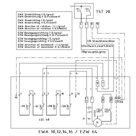
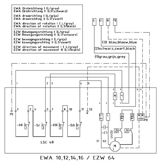
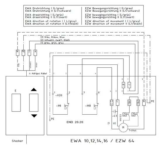
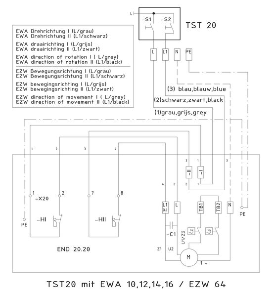
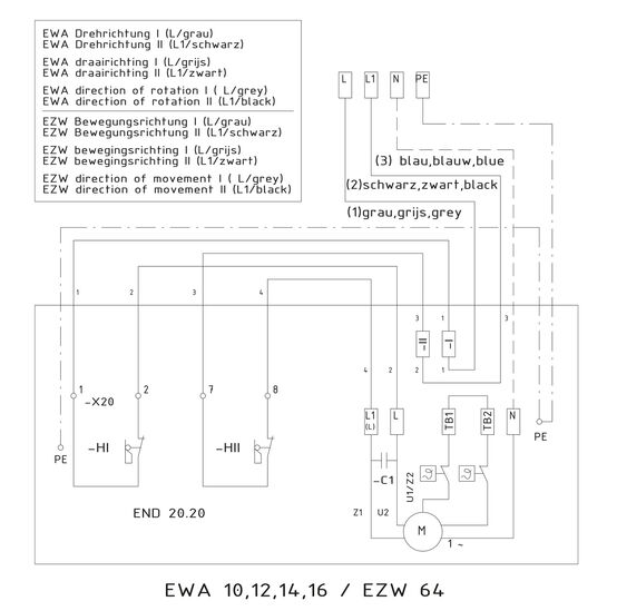
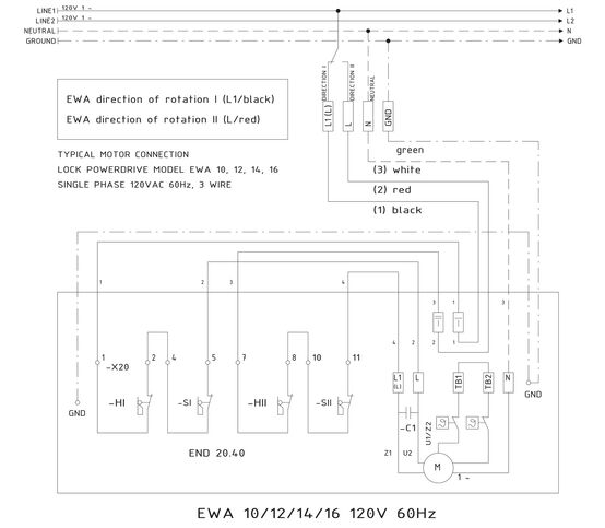
Circuit diagrams: EWA, power drive + TST, switch
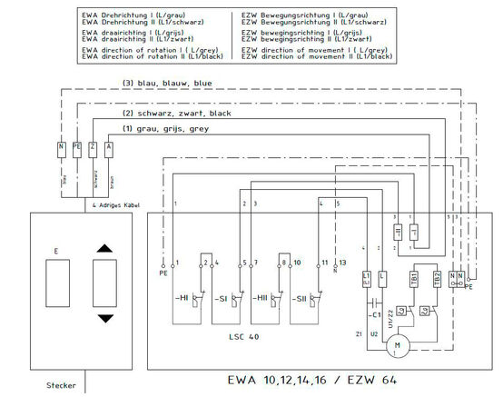
- EWA direction of rotation I (L/grey)
- EWA direction of rotation II (L1/black)
- EZW direction of movement I (L/grey)
- EZW direction of movement II (L1/black)
- EWA direction of rotation I (L/grey)
- EWA direction of rotation II (L1/black)
- EZW direction of movement I (L/grey)
- EZW direction of movement II (L1/black)
- EWA direction of rotation I (L/grey)
- EWA direction of rotation II (L1/black)
- EZW direction of movement I (L/grey)
- EZW direction of movement II (L1/black)
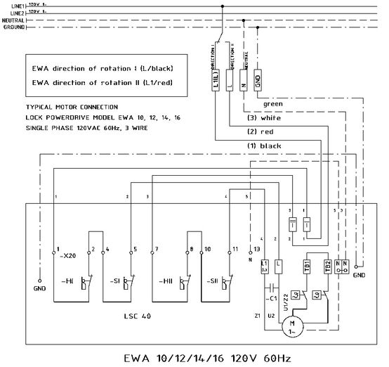
- EWA direction of rotation I (L1/black)
- EWA direction of rotation II (L/red)
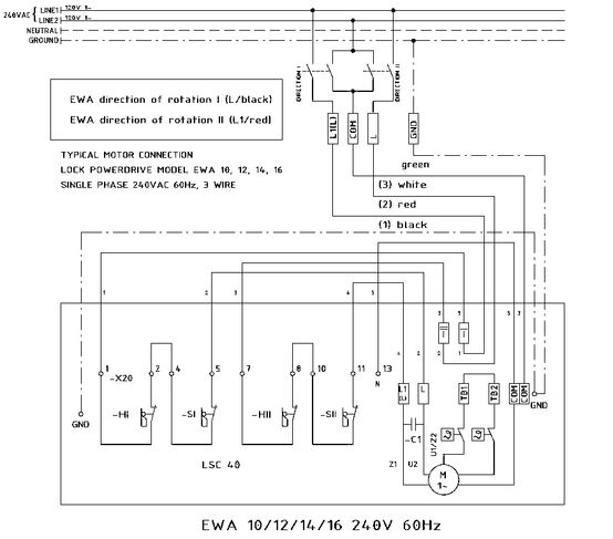
- EWA direction of rotation I (L1/black)
- EWA direction of rotation II (L/red)
Circuit diagrams: END 20.20
- EWA direction of rotation I (L/grey)
- EWA direction of rotation II (L1/black)
- EZW direction of movement I (L/grey)
- EZW direction of movement II (L1/black)
- EWA direction of rotation I (L/grey)
- EWA direction of rotation II (L1/black)
- EZW direction of movement I (L/grey)
- EZW direction of movement II (L1/black)
- Turnkey 1~
- EWA direction of rotation I (L/grey)
- EWA direction of rotation II (L1/black)
- EZW direction of movement I (L/grey)
- EZW direction of movement II (L1/black)
- WSK coil protection contact bridged on terminal strip, can be connected up if required.
- EWA direction of rotation I (L1/black)
- EWA direction of rotation II (L/red)
- WSK coil protection contact on terminal strip is bridged. Can be accessed on demand.
- EWA direction of rotation I (L1/black)
- EWA direction of rotation II (L/red)